7 Dimensioning

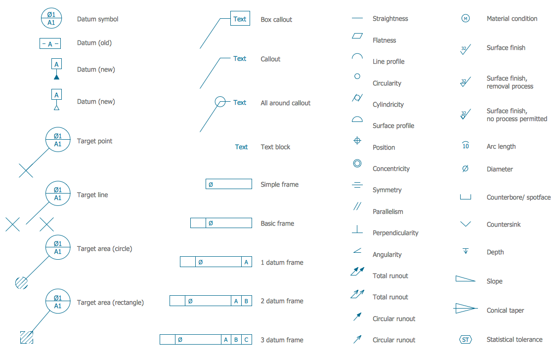
Common Symbols Technical Graphics
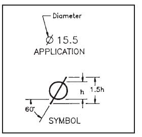
Drawings. ◇civil engineering drawings may be dimensioned in meters. ◇ architectural drawings may use both meters. 8. 5 dimensioning radius 8. 6 simplified dimensioning by co-ordinates 8. 7 arrangement of dimensions week 9 abbreviations in symbols used in mechanical, electrical and building drawing 9. 1 technical drawing symbols 9. 2 conventional symbols 9. 3 line and block diagrams week 10 free hand sketching 10. 1 general notes before sketching. 1. 3 symbol sizes are shown in the figures as values propor-tional to the letter ‘h’. the letter ‘h’ represents the predominant technical drawing radius symbol character height on a drawing. if a symbol dimension is shown as 1. 5h, and the predominant character height on the drawing is to be 3mm, then the symbol dimension is 4. 5mm (1. 5 x 3mm).
The Bell System Technical Journal 19221983 Free Texts
Technical standards exist to provide glossaries of abbreviations, acronyms, and symbols that may be found on engineering drawings. many corporations have such standards, which define some terms and symbols specific to them; on the national and international level, asme standard y14. 38 [1] is one of the widely used standards. More technical drawing radius symbol images. Diameter symbol the diameter symbol indicates a circular feature when used on the field of a drawing or indicates that a defined tolerance is diametrical when used in a feature control frame. dimension a dimension is a numerical value expressed in appropriate units of measure and indicated on a drawing. A compass, also known as a pair of compasses, is a technical drawing instrument that can be used for inscribing circles or arcs. as dividers, they can also be used as tools to measure distances, in particular on maps. compasses can be used for mathematics, drafting, navigation and other purposes.. prior to computerization, compasses and other tools for manual drafting were often packaged as a.
Dimensioning And Notation Dimensioning And Notation Chapter 6
The bell system technical journal was a key enabler for this achievement. with this posting of the bell system technical journal from volume 1 issue 1 in july 1922 to the final issue published in december 1983, we are pleased to be able to open the vault of this knowledge to our global technical colleagues. Diameter symbol replaces the word "diameter". it should be used anywhere there is a diameter on the drawing,abd when a tolerence zone is cylindrical. radius (r)a straight line extending from the center of an arc or circle to its surface. controlled radius (cr) c reates a tolerance zone defined by two arcs (the minimum and maximum radii. Gd&t symbol: relative to datum: yes mmc or lmc applicable: no drawing callout: description: total runout is how much one entire feature or surface varies . Technical drawing specifications resource 3 introduction this resource material is intended to provide advice and support on technical drawing specifications relating to key knowledge and skills in vce visual communication design study 2013-17. the content of this resource document offers guidance for technical drawing.
Aug 08, 2018 · when i saw the term "full rad" on a drawing, the drafter told me that it meant the radius was tangential to both sides of a slot. i now no idea of how the machine shop interpreted it. this is the problem asme y14. 5 addresses.jhg. Jan 3, 2016 buy metric circle radii radius shapes symbols drawing metric radius circle radii technical drawing drafting plastic template stencil for sale . Learners examine the drawing symbols used for counterbore, countersink, spotface, radius, diameter, and depth. in the quiz that completes the activity, they . Engineering drawing abbreviations and symbols are concise and easy to understand for people from any country, also save space and make the drawing looks more pleasing to the eye. technical standards are made to define and provide glossaries of abbreviations, acronyms, and symbols that may be found on engineering drawings.
Metric radius circle radii technical drawing drafting plastic template stencil for sale infographic tools, infographics. Symbols. radius. diameter. square. taper. slope. mec076 engineering drawing interpretation 1. resource package. december, 1998. r. d. r8. r12. 015. 08. Similar to the radius, the diameter symbol symbol is placed in front of the number. for example, Ø50 means that the diameter of a circle is 50mm. in order to draw that circle you will have to divide it in two to get the radius, so you can swing it with your compass.
We hope you like the object in figure 1, because you'll be seeing a lot of it. before we get started on any technical drawings, let's get a good look at this strange block from several angles. figure 1 a machined block. isometric drawing. the representation of the object in figure 2 is called an isometric drawing. The letter 'r' as shown is used widely in drawings and is short for the word radius. radius is the distance from the centre point of a circle to the circumference of .
Rulers used in technical drawing are usually joined by a trammel bar, useful when technical drawing radius symbol drawing very large radius arcs. often a circle template is used instead of a compass when predefined circle sizes are required. templates. templates contain pre-dimensioned holes in the right scale to accurately draw a symbol or sign. letter templates are used.


Each drawing should use the same unit for all dimensions, but without showing the unit symbol. 7. no more it may be indicated by a radius arrow and the symbol r, without an indication of the value (fig. 2. 49). mechanical. mech. a. A hole callout is inserted and the dimension propertymanager appears. the callout contains a diameter symbol and the dimension of the hole diameter. if the depth of the hole is known, the callout also contains a depth symbol and the dimension of the depth. if the hole is created in the hole wizard, the callout contains additional information (the dimensions of a countersink or number of hole. A technical drawing. connect symbols have a significant function in drafting. radius. use the symbol Ø before the dimension. when dimensioning an arc, .
Technical drawing dimensioning types. dimensioning rules is very important for drawing standards. proper dimensioning will help to manufacturers, engineers etc. to get better understanding of the designed parts. selected front view should describe the part. Always given the diameter of a hole, not the radius. a Ø technical drawing radius symbol symbol must be used before the value. coordinate/base line dimensioning: ordinate dimensioning:. May 04, 2021 · introduction. the techdraw workbench is used to produce basic technical drawings from 3d models created with another workbench such as part, partdesign, or arch, or imported from other applications. each drawing is a page, which can contain various views of drawable objects such as part::features, partdesign::bodies, app::part groups, and document object groups.
The scale of a drawing is usually presented as a ratio and is read as illustrated in the following examples. 1" = 1" read as 1 inch (on the drawing) equals 1 inch (on the actual component or system). this can also be stated as full size in the scale block of the drawing. the measured distance on the drawing is the actual distance or size of the. Jun 27, 2014 · arc: any portion of a circle; usually dimensioned according to the radius. background: the first multiline you select to create a closed cross intersection. base point: the initial reference point autocad uses when stretching, moving, copying, and scaling objects. block: a symbol or shape saved and stored in a drawing for repeated use. circle. 1 feb 1997 figures are not complete technical drawings. these simplified tolerances are specified, and each symbol has a clearly defined meaning. the 1994 standard to indicate a controlled radius dimension. caution this .


0 komentar:
Posting Komentar